I have a new toy, seriously, I want to switch some 230V devices in my basement. I got this card for that; the board has four switching relays and especially a 230V power supply on the board. But it’s a little tinkering. If you can’t or don’t want to solder, you should look for another board.
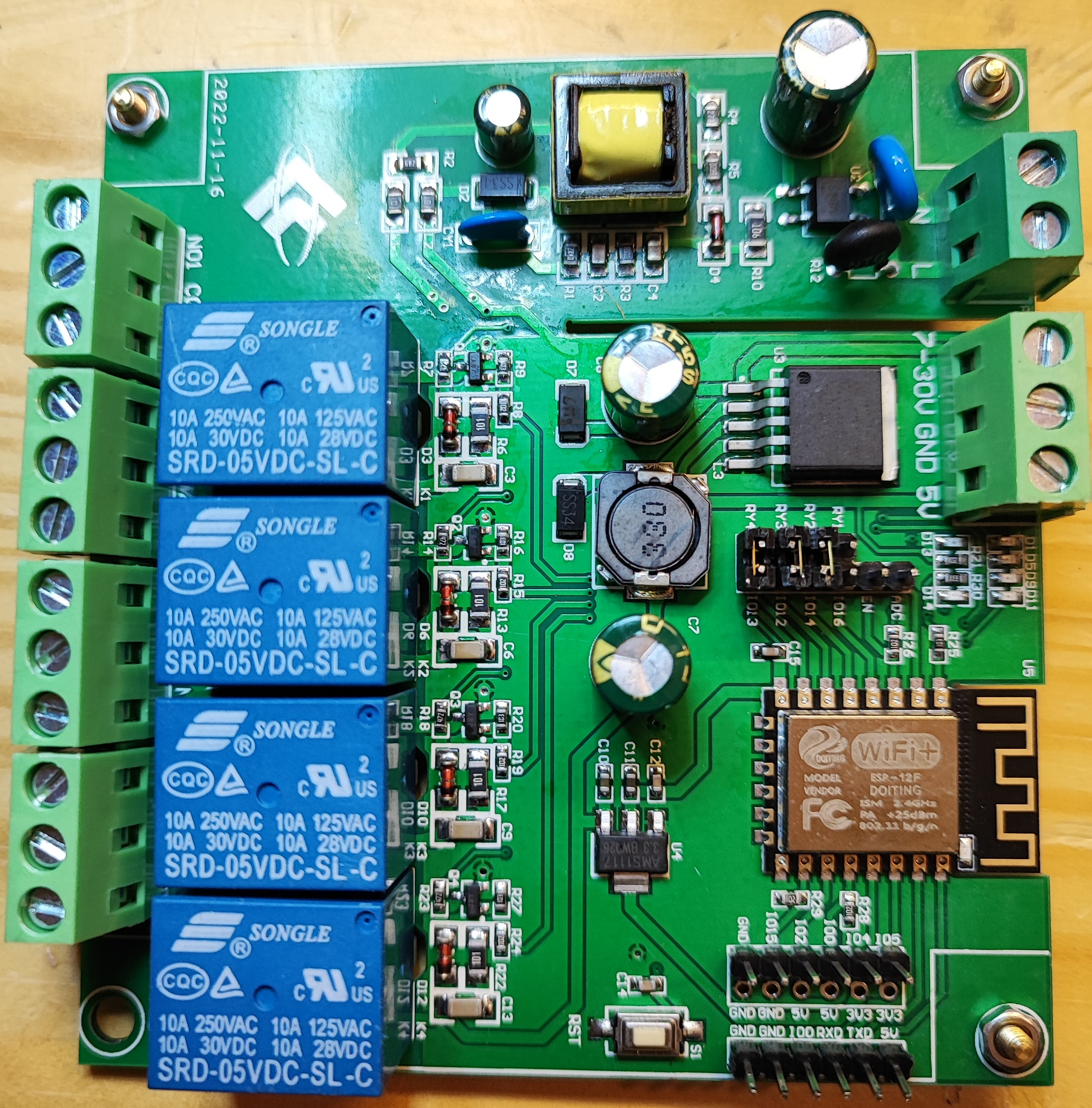
The board does not have a USB port, so no firmware can be uploaded directly. And not only that, the pin headers for the connections are not soldered either, but they were included.
So, the pin headers must be soldered to the circuit board first. By now everyone should keep their hands off the board if they don’t want to tinker or can’t solder
In the picture, the pin headers are already soldered in and the jumpers are set.
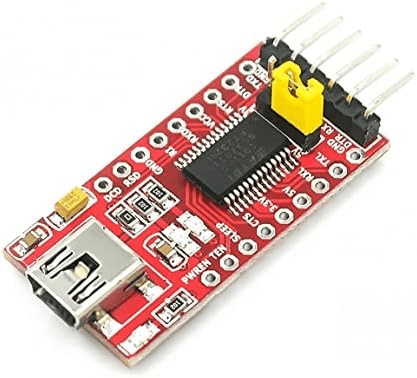
To establish a USB connection with the board, a so-called “FTDI USB to TTL Serial Adapter” is now required, which is connected between the board and our computer to be able to upload the first firmware. I took an FTDI adapter that can supply 3.3V & 5V boards with power when flashing the firmware, here you must make sure that the correct voltage is used. With this USB adapter, the voltage can be switched between 3.3V and 5V using the jumper on the board. The board could also be supplied with a suitable power supply via the screw terminals.

Now connect the USB adapter to the relay board, I’ve created a picture of it.
TX-RX / RX-TX / GRD-GRD / VCC-5V these connections are required for uploading the firmware.
The jumper is board specific; many boards require a jumper for the board to accept firmware flashing or flashing.

The outputs of the ESP32 must be connected to the switching inputs of the relays on the circuit board. To do this, the connector strips must be soldered in the middle of the board and then the connections can be plugged in with jumpers.
When switching on the board, relay 1 switches briefly. I found at https://te mplates.blakadder.com/ESP12F_Relay_X4.html that the board gives a short pulse to PIN 16 when it is switched on. The problem can be solved with a bridge between the relay and PIN 15, adjust the pin assignment for relay 1 in the YAML code and it works.
Now we can build the firmware, at ESPHome.io I got a template for the YAML code again, and the board was perfectly running.
esphome:
  name: relayboard
  platform: ESP8266
  board: esp12e

# Use the blue LED in the device as a status LED, which will blink if there are warnings (slow) or errors (fast)
status_led:
  pin:
    number: GPIO5
    inverted: True

# Four relay outputs, exposed as switches in Home Assistant
switch:
  - platform: gpio
    pin: GPIO15
    name: Relay1
    id: relay1
  - platform: gpio
    pin: GPIO14
    name: Relay2
    id: relay2
  - platform: gpio
    pin: GPIO12
    name: Relay3
    id: relay3
  - platform: gpio
    pin: GPIO13
    name: Relay4
    id: relay4